Electrical trace heating uses a purpose-designed heating cable fitted to pipework, vessels or equipment to replace heat that is lost to the surrounding environment. It is commonly used either to stop water and process lines freezing or to keep a product within a required temperature range.
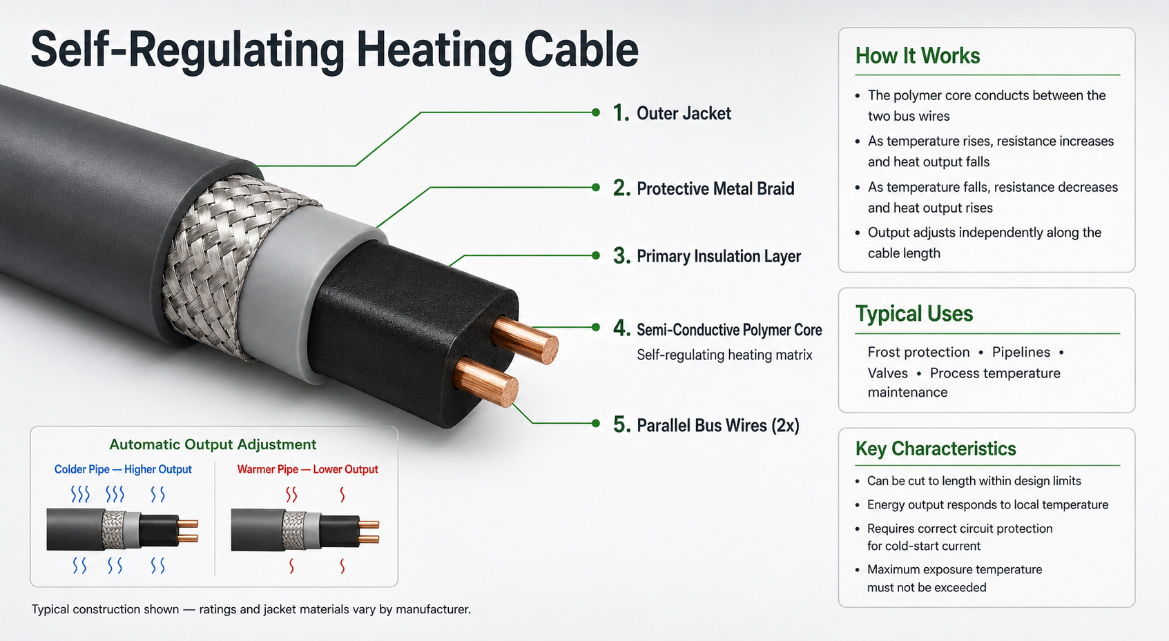
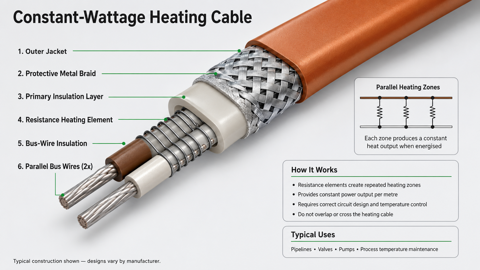
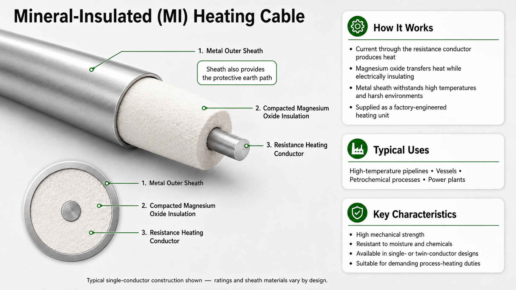
It works by having a matrix between the two conductors or a set resistance between the two conductors for constant wattage cable. Mineral insulated (MI) cables are a set resistance element, similar to how electric heaters work.
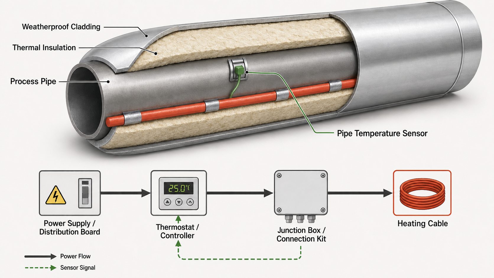
The cable is only one part of the system. A reliable installation also depends on the electrical supply, controls, sensors, circuit protection, correct attachment, thermal insulation, weatherproofing, testing and commissioning.
How a trace heating system works
When energised, the heating cable converts electrical energy into heat. This heat transfers into the pipe or equipment and offsets heat loss through the insulation and outer cladding. A thermostat or electronic controller may switch the circuit based on ambient temperature, pipe temperature or process conditions.
The required heat output is not determined by pipe diameter alone. Designers consider:
- Lowest ambient temperature
- Required maintain temperature
- Pipe material and size
- Insulation type and thickness
- Wind exposure
- Hazardous area classification
- Circuit length and available voltage
- Valves, supports and other heat sinks
Where electrical trace heating is used
Typical applications include exposed water lines, critical instruments, fire water and washdown pipework, dosing and sampling lines, condensate drains, instrument lines, chemical processes, tanks, hoppers and vulnerable valves.
In utilities and industrial environments, the goal is continuity of service. A frozen or under-temperature line can interrupt production, damage equipment or create safety and environmental risks.
The main cable types
Self-regulating cable — Adjusts its heat output in response to local temperature. Widely used for frost protection and many temperature maintenance duties.
Constant wattage cable — Provides a fixed output per unit length and requires careful design and control.
Mineral insulated cable — Suited to demanding duties, high temperatures and harsh environments. Installation and termination are more specialised.
Choosing the correct cable depends on the application. "More powerful" is not automatically better — excessive surface temperature, unsuitable materials, poor control or overlong circuits can create reliability and compliance issues.
Why insulation matters
Trace heating replaces heat loss; insulation reduces that heat loss. Without the specified insulation, the installed heating cable may not maintain the target temperature, even if the electrical circuit is functioning correctly. Wet, damaged or missing insulation can therefore appear to be a trace heating fault.
What a professional installation should include
A competent installation should:
- Follow the approved design and manufacturer instructions
- Use suitable power and end terminations
- Position sensors correctly
- Protect cables from mechanical damage
- Identify traced circuits clearly
- Record electrical tests
Commissioning should demonstrate that the circuit, controls and protection operate as intended, and leave usable records for future maintenance.
For hazardous areas or critical process duties, equipment selection, installation and inspection must also match the site classification and applicable standards.
Key takeaway
Electrical trace heating is a complete engineered system, not simply a cable attached to a pipe. When design, installation, insulation and controls work together, it provides dependable frost protection or temperature maintenance with a clear route for inspection and maintenance.
Frequently asked questions
Does trace heating stay on all the time? Not necessarily. Many systems use thermostatic or electronic control, while some self-regulating circuits are energised seasonally. The control strategy should match the duty and energy requirements.
Can trace heating be fitted to plastic pipe? Yes, for suitable applications, but cable type, output, attachment method and heat transfer must be checked carefully against the pipe and manufacturer requirements.
Is trace heating the same as insulation? No. Trace heating adds heat; insulation slows heat loss. In most applications they are designed to work together.
Need support with a new installation, a system fault or planned maintenance? Speak to TA Thermal on 0115 683 9540 or email info@tathermal.co.uk.